Electrical Design
Microcontroller
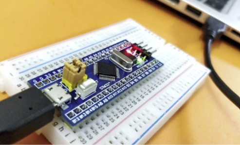
As for the microcontroller, we used a Blue Pill STM32, with a 72 MHz clock speed. This microcontroller has 64 KB of flash memory and 20 KB of SRAM. It has 37 GPIO pins, 10 of which are analog pins. It also has 3 UART ports, 2 I2C ports, and 2 SPI ports. We chose this microcontroller because it is very powerful and has a lot of pins. It is also very cheap, which is a bonus.
KiCAD and PCB Design
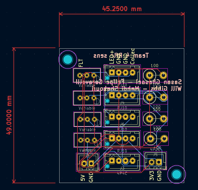
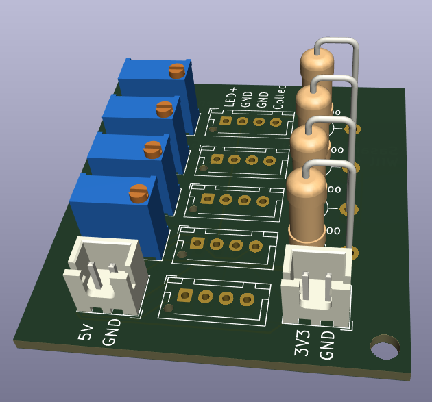
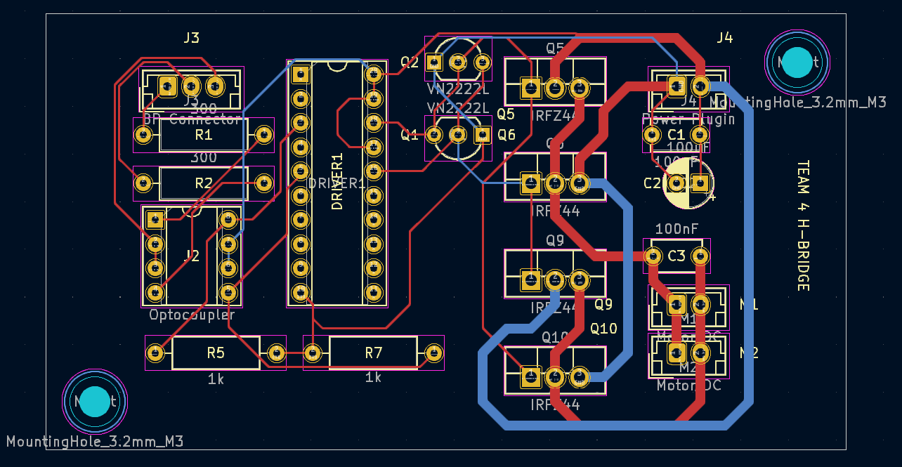
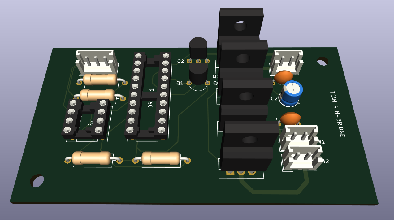
We used KiCAD to design the PCB for our robot. KiCAD is an open source software that allows you to design PCBs and schematics. It is a very powerful tool that allows you to design complex PCBs. We used it to design multiple PCB's for our robot. We designed a PCB for our motor drivers (H-Bridge), a PCB for reflectance sensors and a PCB for IR detection board.

H-Bridge
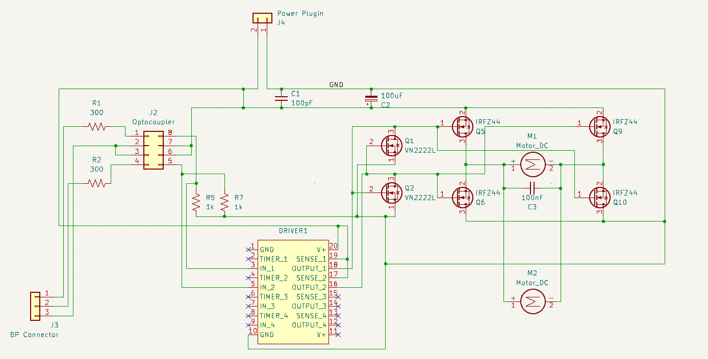
The H-Bridge circuit is used to control the direction of the motor. The H-Bridge circuit consists of 4 IRFZ44 MOSFETs and two VN2222L MOSFETs. The VN2222L MOSFETs are connected to Quad Protected High-side Mosftet Driver which has a supply range of 8V to 48V. This special type of driver allows us to use low cost N-channel power MOSFETs for high-side switching applications. The IRFZ44 MOSFETs are used to drive the motor and they turn on and off in pairs.
We used the Blue-pill to send PWM signal to the motor and control its speed. However, the microcontroller is very sensetive to noise and cannot be run with the high voltage that is connected to the motor. Therefore, we used an optocoupler to isolate the microcontroller from the motor. The optocoupler is a device that transfers electrical signals between two isolated circuits by using light. The optocoupler is connected to the microcontroller and the H-Bridge circuit. The optocoupler is used to send the PWM signal to the H-Bridge circuit.
To minimize noise issues we added some capacitors on the positive and negative terminals of the motor. We also added a 100uF and 100pf capacitor on the power supply of the H-Bridge circuit.
Reflectance Sensors
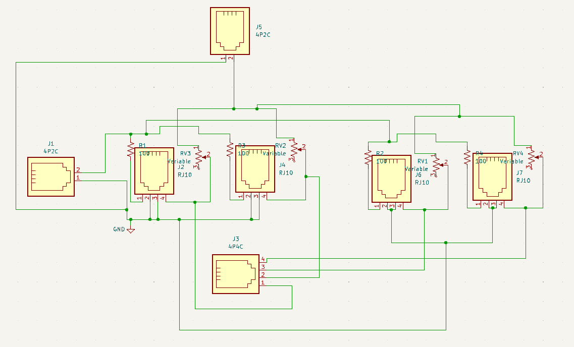
The reflectance sensor circuit is used to detect the black line on the ground. The circuit consists of 4 IR LEDs and 4 IR phototransistors. The IR LEDs are used to emit infrared light and the IR phototransistors are used to detect the infrared light. The IR phototransistors are connected to the microcontroller and the microcontroller reads the voltage on the IR phototransistors. When the IR phototransistor is over the black line, the voltage on the IR phototransistor is low. When the IR phototransistor is over the white surface, the voltage on the IR phototransistor is high.
We used variable resistors on the reflector sensors to adjust the sensitivity of the sensors, since in different environments, based on ambient light and the colour of the surface, the sensitivity of the sensors changes.
In addition, for ease of use, we added JST connectors to all our PCBs and circuit boards. This allows us to easily connect and disconnect the PCBs and circuit boards from the robot, which makes it easier to debug and fix issues.
